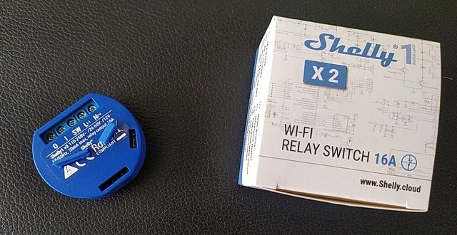
Shelly One and Tasmota
Today I automated the switch for the swimming pool and replaced a timer clock. We have a small solar panel for heating the swimming pool which should only be on if the sun is shining and the pool pump is on too. The swimming pool pump should be on for a lot longer than the solar panel, which is why I need to separate timer clocks.
Or 2 Shelly Ones.

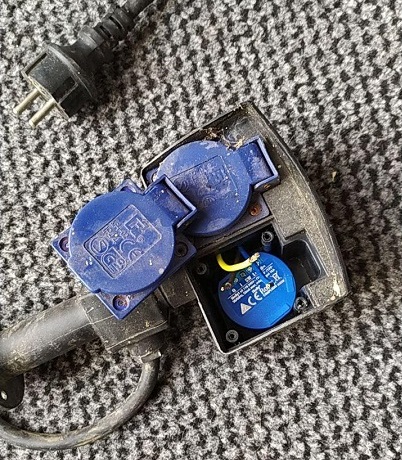
Two Shelly One can fit into this double socket 
Those need to be wired quite stupid as there is not much room left in the socket for two Shellys besides the normal plug socket.
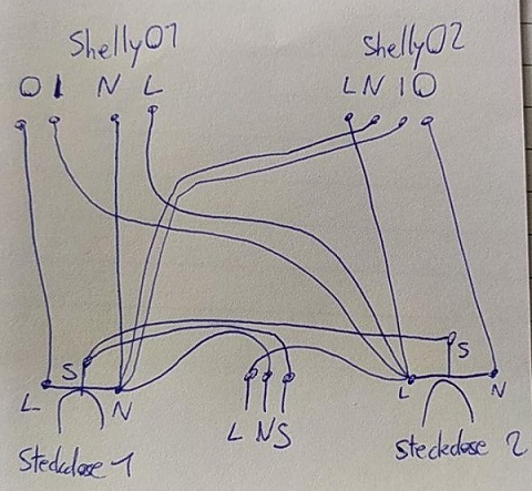
This is a small outline of the wiring I did:

So the left socket is switched on N while the other one is switched normally on L.
Flashing wiring
But before Wiring we have to flash the firmware on the device.
We will use Tasmota, as it is quite common used and has a lot of Features (integrates quite nicely with MQTT and Home-Assistant)
Flashing is very simple on the shellys as they have open pins for RX, TX, GPIO0, GND and 3.3V input.
In most Tutorials an FTDI is used to flash an ESP8266, but as I don’t have one at hands I will use a different approach.
Using a Wemos D1 mini we can connect the RST - GND, which stops booting the ESP8266.
This allows to bridge the RX, TX, GND, 3.3V and connect the Shelly to the Wemos D1 mini.
To boot the Shelly into Flash mode we need to connect the GPIO0 to GND. This setup works with every ESP8266 and is a very nice trick if you haven’t got an FTDI adapter.
So the wiring is:
D1mini:
- RST - GND
between D1mini - Shelly1
- 3.3V - 3.3V
- GND - GND
- TX - TX
- RX - RX
- GND - GPIO0 (for flash mode)
Flashing Tasmota
For the flashing I used the official release binaries tasmota.bin.
I flashed it using the tasmotizer which is a bundled windows binary of esptool for flashing tasmota firmware via a COM port.